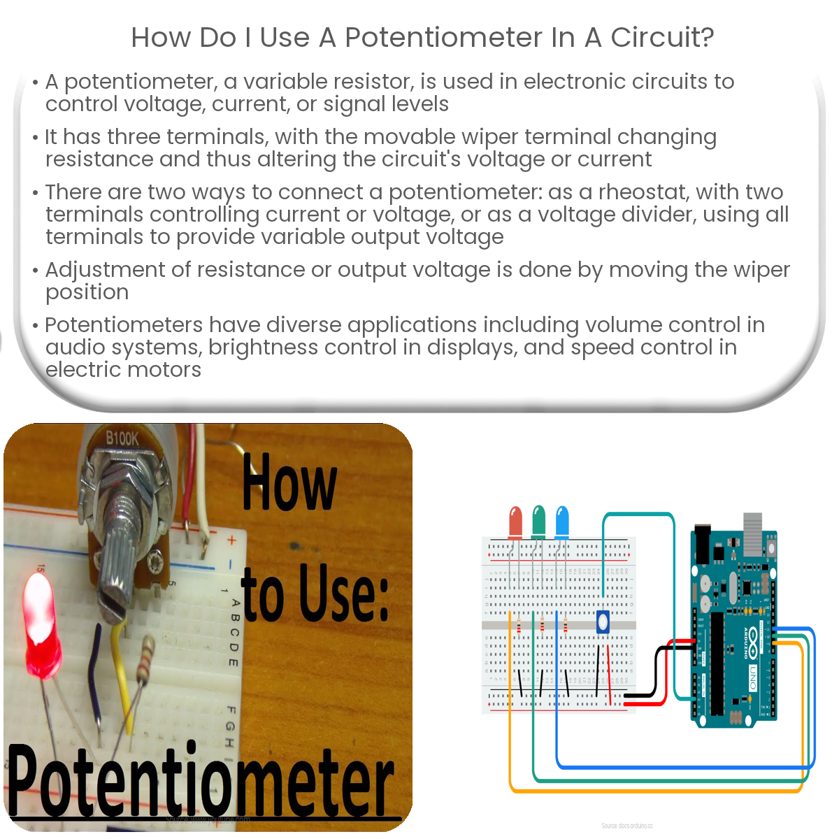
How Does A Potentiometer Work In Circuit Circuit Diagram Learn how to connect, read, and use a potentiometer as an analog input for your Arduino projects. See how to create a color mixer and a cross-fader with a potentiometer and LEDs.

Learn what a potentiometer is, how it works, and how to use it in different circuits. See the inside of a potentiometer, the different types, and wiring examples for volume control, LED dimming, and more. Learn how to use a potentiometer as a variable resistor or a voltage divider with examples and diagrams. Find out the difference between linear and logarithmic tapers and how to calculate the output voltage.
Potentiometer Explained Circuit Diagram
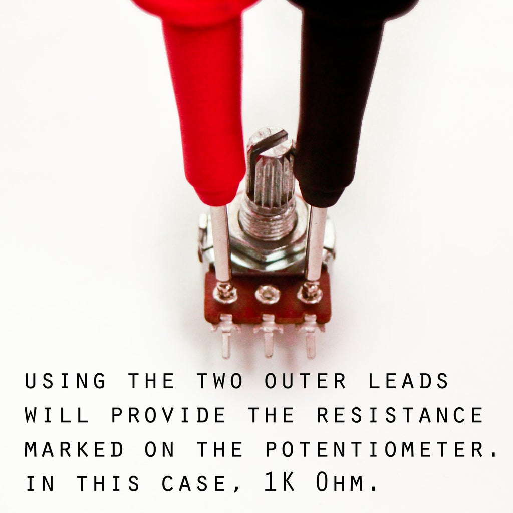
Sometimes, you can use a pot to overclock a device with a stronger signal. 2. Read the resistance numbers printed on your pot to see what range you can achieve. Pots are rarely used to control signals that are more than a couple of volts, but the amount of resistance that they provide is important. The higher the range, the more control you Learn the basics of potentiometers, variable resistors with three terminals, and how they work. Explore the different types of potentiometers, such as rotary, linear, and digital, and their applications in electronics.

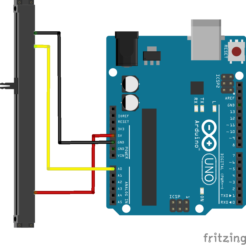
Learn how to test the reference ohms of a potentiometer by rotating its knob clockwise and anticlockwise. Watch as we measure resistance changes and understa This is the potentiometer. It can be a little awkward to fit into a breadboard, so consider soldering new connections to the pins (don't forget to color code). Using your potentiometer . It has three pins. The outer two pins work much like any resistor - they can be connected in either direction and to either Ground or Power. We use potentiometers as voltage dividers or current limiters. With a voltage divider, we connect the power supply across the two end pins, and the wiper connects to the centre pin. This pin provides our output voltage. If we connect our multimeter to this output and to ground, we can see the output voltage varies as we rotate the shaft.
Tutorial: Using a potentiometer Circuit Diagram
A Potentiometer can work as a Rheostat by making use of just two of its terminals: One is the Wiper and the other is either of the two outer terminals. In this case, the POT acts as a two terminal variable resistor. The value of the resistance increases or decreases by turning the Wiper. Voltage Divider Potentiometer Wiring Diagram