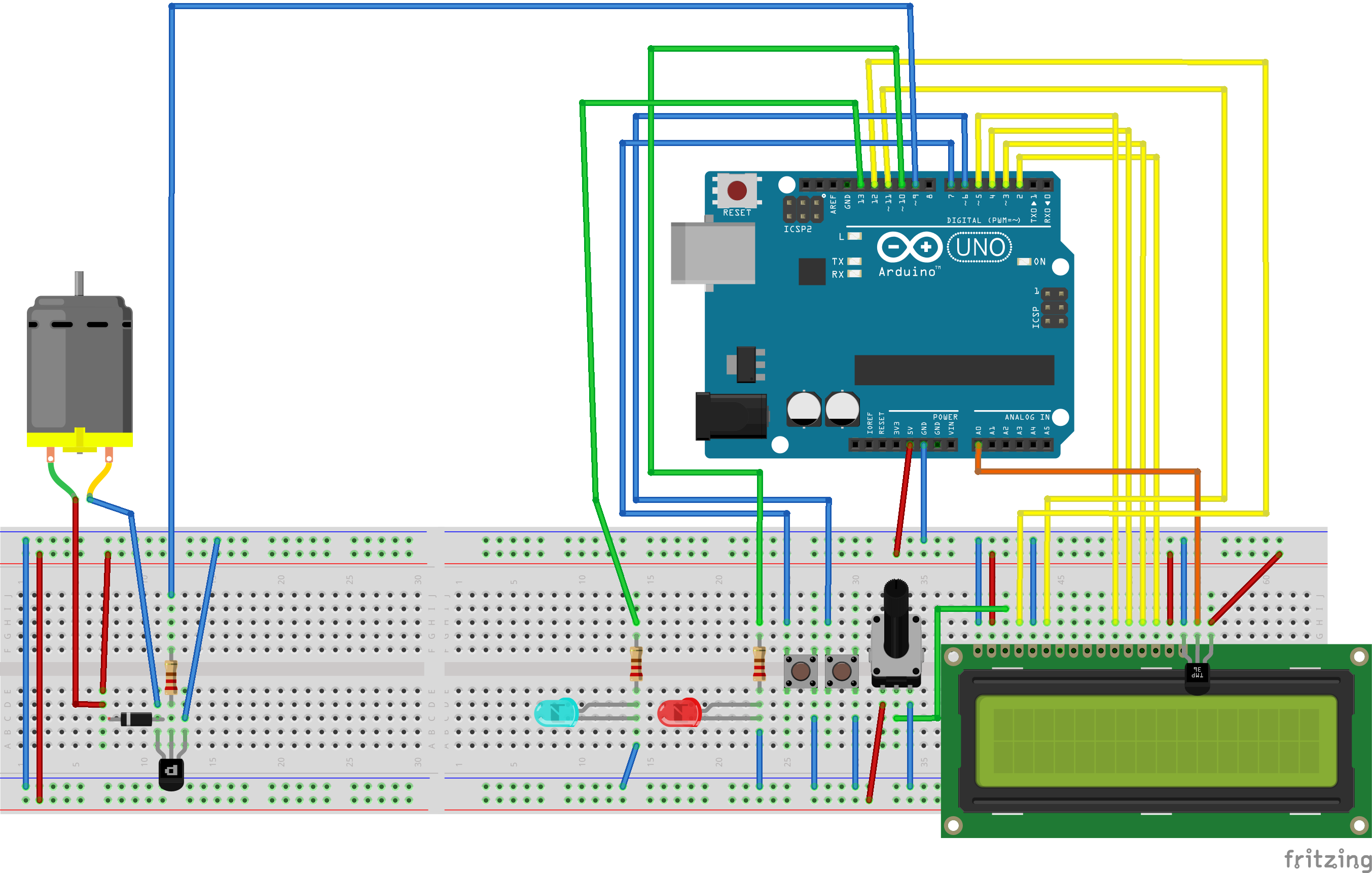
Temperature Sensor With LED 7 Steps Circuit Diagram Hello to everyone, a little help please? I want to build a thermistor temp sensor using arduino (as in above circuit) but then need to convert measured temperature in degrees centigrade to air flow in meters per second, and be able to display on screen, and record this via computer. Any help suggestions greatly appreciated. regards Andrew

You may create a temperature meter circuit that drives LEDs through the LM3915 display driver by utilizing these calculations and recommendations and the LM35 temperature sensor. To achieve accurate temperature indication, test the circuit thoroughly and adjust component values according to individual needs. How to Build: To build a Simple

Temperature Sensor Tutorial! : 5 Steps (with Pictures) Circuit Diagram
The following post explain how to build a simple temperature indicator using a 1 mA moving coil meter and a few transistors and resistors. The sensor device in this project is the diode 1N4148. How it Works. In the above temperature meter circuit, a 1N4148 diode is employed to sense the temperature.

Using basic electronic sensors, we can build our own heat detector. The main component, which is the LM35DZ temperature sensor, is used to measure the current room temperature. Based on the measurement, the detector will warn the user using other sensors such as the buzzer and the LED to indicate whether the room temperature exceeds the limit A thermistor would be ideal for your remote weather stations project, home automation systems, temperature control, protection circuit, etc. In this tutorial, I will explain how a thermistor works and how you can build a small circuit with Arduino and a thermistor that displays the temperature on the serial monitor or on an LCD display.
Simple Temperature Indicator Circuits using Thermistors Circuit Diagram
Connecting to your temperature sensor These sensors have little chips in them and while they're not that delicate, they do need to be handled properly. Be careful of static electricity when handling them and make sure the power supply is connected up correctly and is between 2.7 and 5.5V DC - so don't try to use a 9V battery! breadboarded to-92 - In this tutorial, we are making a project of a Simple temperature sensor circuit. This circuit activates an LED when it senses or receives heat so you can also call this circuit a heat sensor circuit. Apart from its uses, If you are a beginner who just wants to make an easy and interesting project this circuit is ideal for you.